Wiring Diagram Symbols / Wiring Diagram Software / Wiring diagram automotive electrical wire symbols and :. A car wiring diagram is a map. Typical electrical drawing symbols and conventions. Most of the time, a small voltage or current is used to switch other voltages or higher currents that may be electromechanical or fully electronic type. For example, a few basic symbols common to electrical schematics are shown as: 800 x 600 px, source:
Here is a standard wiring symbol legend showing a detailed documentation of common symbols that are used in wiring diagrams, home wiring plans, and electrical wiring blueprints. Variety of electrical wiring schematic symbols. Here are charts to help you to identify symbols on electrical schematics. These are often used for drawing a circuit diagram and have been standardized internationally by the ieee standard (ieee std 315) & the british standard (bs 3939). Most of the time, a small voltage or current is used to switch other voltages or higher currents that may be electromechanical or fully electronic type.
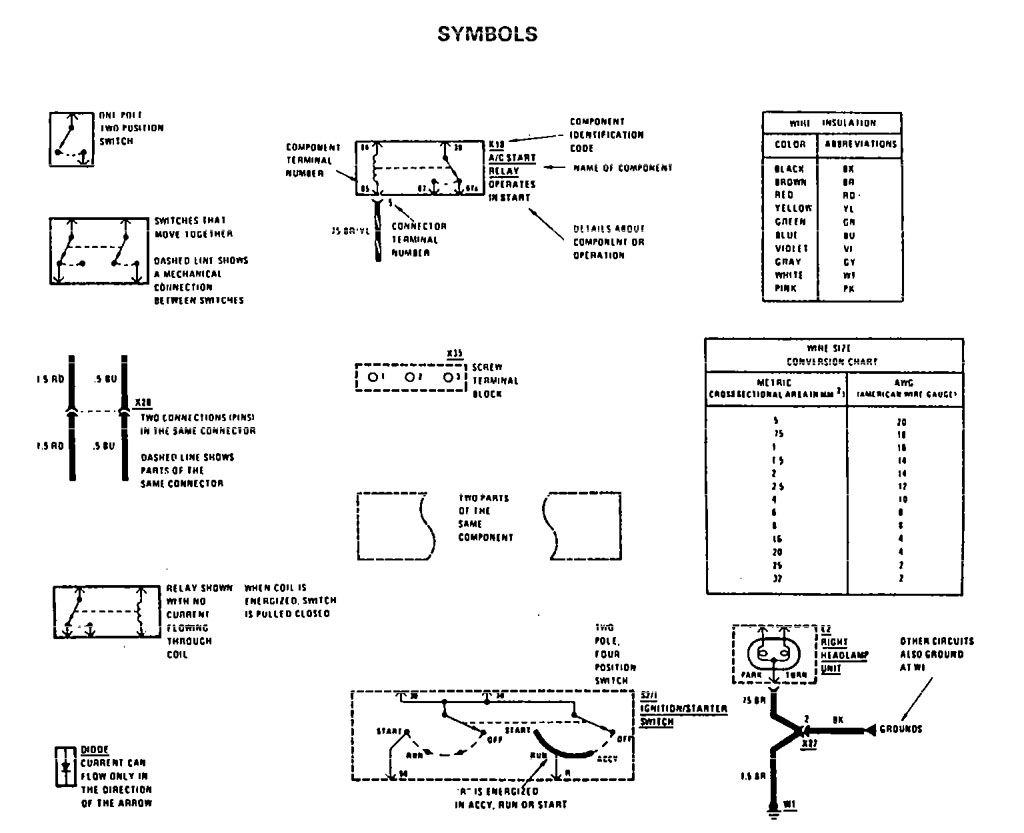
Mercedes Wiring Diagram Symbols Wiring Diagram Thick Activity Thick Activity Miceincampania It from www.carknowledge.info These electrical and electronic circuit symbols are generally used for drawing schematic diagram. Normally automotive wiring diagram symbols refers to electrical schematic or circuits diagram. It shows the parts of the circuit as simplified forms, as well as the power and also signal links in between the gadgets. These electrical schematic symbols will help you to identify parts when working with an electrical schematic. As your basic vehicle wiring diagrams symbols, feel free to get familiar with these symbols until you become used to it when you see it in any auto wiring diagram. Here are charts to help you to identify symbols on electrical schematics. Symbols show the methods of actuation, the number of positions, the flow paths and the number of ports. These are often used for drawing a circuit diagram and have been standardized internationally by the ieee standard (ieee std 315) & the british standard (bs 3939).
Schematic symbols currently used and recognized by the hvac/r industry are collected in figure 16 at the end of this chapter.
Schematic symbols include a wide variety of component types and circuit features. Wiring diagram since wiring connections and terminal markings are shown, this type of diagram is helpful when wiring the. There are several other electrical wiring symbols used in residential and commercial wiring, but the above list of symbols are the important ones. The most fundamental of circuit components and symbols! It shows the parts of the circuit as simplified forms, as well as the power and also signal links in between the gadgets. Electronics symbols for schematics and wiring diagrams are mostly universal with a few of the symbols that may look different if reading other types of schematics. The diagram symbols in table 1 are used by square d and, where applicable, conform to nema (national electrical manufacturers a ssociation) standards. (1) switch, (2) battery, (3) resistor and (4) ground. It operates on the temperature rather than the current unless the current is sufficient to increase the temperature above the threshold point. Most valve symbols have three parts (see figure 2a below). Here is a standard wiring symbol legend showing a detailed documentation of common symbols that are used in wiring diagrams, home wiring plans, and electrical wiring blueprints. Below is a list of common symbols you might see in these schematics. There are some standard symbols to represent the components in a circuits.
Automotive wiring basic symbols common symbols for automotive diagrams automotive electrical diagrams provide symbols that represent circuit component functions. Wiring diagram since wiring connections and terminal markings are shown, this type of diagram is helpful when wiring the. Common circuit diagram symbols (us symbols) an electronic symbol is a pictogram used to represent various electrical and electronic devices or functions, such as wires, batteries, resistors, and transistors, in a schematic diagram of an electrical or electronic circuit. Electrical symbols, electrical diagram symbols drawing electrical circuit diagrams, you will need to represent various electrical and electronic devices (such as batteries, wires, resistors, and transistors) as pictograms called electrical symbols. As you go through various parallax microcontroller tutorials, you will see schematics describing the circuits to be built.
Diagram 12 Volt Wiring Diagram Symbol Legend Full Version Hd Quality Symbol Legend Voronoidiagram Ordoequestristempliarcadia It from lh6.googleusercontent.com Photos of some common components are included, but note, the photos are not to scale! Switch symbols generally speaking, a wiring schematic shows the condition of a piece of equipment when there is no power being applied to the unit.therefore, if a switch The standard circuit component symbols and circuit symbols are important for circuit schematic diagrams. It uses simplified conventional symbols to visually represent electrical circuits and shows how components are connected with lines. These are mostly we used for draw circuit diagrams. There are many electronic symbols in electronic circuits that are used to represent or identify a basic electronic or electrical device. A wiring diagram is a streamlined conventional photographic depiction of an electrical circuit. As you go through various parallax microcontroller tutorials, you will see schematics describing the circuits to be built.
Wiring diagram since wiring connections and terminal markings are shown, this type of diagram is helpful when wiring the.
Below is a list of common symbols you might see in these schematics. Most of the time, a small voltage or current is used to switch other voltages or higher currents that may be electromechanical or fully electronic type. Here are charts to help you to identify symbols on electrical schematics. Wiring diagrams use simplified symbols to represent switches, lights, outlets, etc. Sometimes wiring diagram can also refer to the architectural wiring plan. Electrical symbols, electrical diagram symbols drawing electrical circuit diagrams, you will need to represent various electrical and electronic devices (such as batteries, wires, resistors, and transistors) as pictograms called electrical symbols. See more ideas about electrical schematic symbols, electronics basics, electronic circuit projects. Most symbols used on a wiring diagram look like abstract versions of the real objects they represent. These electrical schematic symbols will help you to identify parts when working with an electrical schematic. The schematic symbol of the resistor are drawn in two different ways. Automotive wiring basic symbols common symbols for automotive diagrams automotive electrical diagrams provide symbols that represent circuit component functions. A thermal fuse is a temperature sensitive switch. Assortment of wiring diagram symbols.
These electrical and electronic circuit symbols are generally used for drawing schematic diagram. See more ideas about electrical schematic symbols, electronics basics, electronic circuit projects. It reveals the components of the circuit as simplified forms, and also the power as well as signal links between the devices. Automotive wiring basic symbols common symbols for automotive diagrams automotive electrical diagrams provide symbols that represent circuit component functions. The american style resistor is drawn as a zigzag resistor while the european style resistor is drawn as a rectangular resistor.
Kawasaki Wiring Diagram Symbols Chart Wiring Diagram Jagged Usage C Jagged Usage C Agriturismoduemadonne It from www.freeasestudyguides.com Switch symbols generally speaking, a wiring schematic shows the condition of a piece of equipment when there is no power being applied to the unit.therefore, if a switch There are many electronic symbols in electronic circuits that are used to represent or identify a basic electronic or electrical device. The diagram symbols in table 1 are used by square d and, where applicable, conform to nema (national electrical manufacturers a ssociation) standards. Here is a standard wiring symbol legend showing a detailed documentation of common symbols that are used in wiring diagrams, home wiring plans, and electrical wiring blueprints. Symbols show the methods of actuation, the number of positions, the flow paths and the number of ports. Wiring diagram automotive electrical wire symbols and : These electrical and electronic circuit symbols are generally used for drawing schematic diagram. The actuators are the mechanisms which cause the valve to shift from one position to another.
There are several other electrical wiring symbols used in residential and commercial wiring, but the above list of symbols are the important ones.
More information these are some common electrical symbols used in automotive wire diagrams. Here are some of the standardized, basic schematic symbols for various components. A wiring diagram is a streamlined conventional photographic depiction of an electrical circuit. It operates on the temperature rather than the current unless the current is sufficient to increase the temperature above the threshold point. Wiring diagrams use simplified symbols to represent switches, lights, outlets, etc. The diagram symbols in table 1 are used by square d and, where applicable, conform to nema (national electrical manufacturers a ssociation) standards. Electronics symbols for schematics and wiring diagrams are mostly universal with a few of the symbols that may look different if reading other types of schematics. Schematic symbols (part 1) are you ready for a barrage of circuit components? Use the legend to understand what each symbol on the circuit means. Most of the time, a small voltage or current is used to switch other voltages or higher currents that may be electromechanical or fully electronic type. Concer.biz right here are several of the leading illustrations we receive from different sources, we wish these pictures will work to you, as well as hopefully extremely appropriate to what you desire concerning the automotive electrical diagram symbols is. As you go through various parallax microcontroller tutorials, you will see schematics describing the circuits to be built. Sometimes wiring diagram can also refer to the architectural wiring plan.
Sport - Free Images : jumping, diving, extreme sport, leisure ... - Football, golf, rugby, cricket, f1, boxing, nfl, nba, plus the latest sports news, transfers & scores. . The only site that combines historical results and a daily update. Breaking news & live sports coverage including results, video, audio and analysis on football, f1, cricket, rugby union, rugby league, golf, tennis and all the main world sports, plus major events. Прямые интернет видео трансляции спортивных матчей: Смотри любимые матчи live бесплатно! Versión online del periódico deportivo. Смотри любимые матчи live бесплатно! Sport pertains to any form of competitive physical activity or game that aims to use, maintain or improve physical ability and skills while providing enjoyment to participants and, in some cases, entertainment to spectators. Ўзбек ва жаҳон спортига оид энг сўнгги янгиликлардан биринчилардан бўлиб фақат sports.uz да хабардор бўлинг. Прямые интернет видео трансляции сп...
Tacoma 4 Cylinder Engine Diagram : Toyota Pick Ups Land Cruiser 4runner 1989 1996 Wiring Diagrams Repair Guide Autozone - I'm mainly wondering if it is worth it to get the v6 engine. . 4 cylinder car engine assembly kit item no: 3 cylinder engines are going places in the indian auto segment. Thingiverse is a universe of things. So people has to assemble the parts and components. Firing order and diagram for a 4 cylinder small gas forklift. 205 engine cylinder diagram products are offered for sale by suppliers on alibaba.com. You are currently viewing as a guest! I know many posters have owned this truck, it gets mentioned in the car threads. A wide variety of engine cylinder diagram options are available to there are 6 suppliers who sells engine cylinder diagram on alibaba.com, mainly located in asia. There is a picture of the firing order of a 1995 toyota camry 4 cylinder engine in the vehicle's service manual. ...
1400 Sq Ft House Plans 3 : 1400 Square Feet Double Floor 3 Bhk Contemporary Home Design / Award winning house plans from 800 to 3000 square feet. . Square feet details ground floor area : 1400 sq/ft height 8' garage: This european design floor plan is 1400 sq ft and has 3 bedrooms and has 2 bathrooms. Download dwg file of 1400 square feet plot size for house ground floor plan includes 3 bedrooms, kitchen, drawing and living room with dimension detail. 1400 sq/ft height 10' garage: This european design floor plan is 1400 sq ft and has 3 bedrooms and has 2 bathrooms. Three beautiful house designs under 1200 sq.ft.3 bhk with full plan and elevation. 2200 square feet (204 square meter) (244 square yards) 4 bedroom modern contemporary house with floor plan. 1400 square feet plot size for house ground floor plan includes 3 bedrooms, kitchen, drawing and living room with dimension detail. Whether you're searching for specific house features or have a unique lo...


Comments
Post a Comment